Everything on model trains, model railroads, model railways, locomotives, model train layouts, scenery, wiring, DCC and more. Enjoy the world's best hobby... model railroading!
LED Turnout Indicators
Club member Russell sent in this tip to share:
 Light the indicators in the track can be a handy way of knowing which way a turnout gets thrown. You can buy tiny LEDs that are small enough to be unobtrusive, but can still be easily seen. If you think this looks unprototypical (with LEDs in the track), you could install them on your bench work fascia, next to the turnout, or perhaps in a building, or even have them as lights on a pole that respond when the turnout gets thrown.
The LEDs can be positioned between the track rails after both rails and the frog are gapped beyond that point. Small tubes can be used to carry the wiring from the LED up through the foam sub-roadbed. A small blob of Walthers Goo will keep them in position to avoid interference with couplers or other parts on the trains passing above them.
You could use this with electrically powered turnouts, which would save installing relays, or needing a second set of contacts. Some operators find manually controlled double slip switches confusing, so this could be helpful with that too.
For DCC help and advice http://www.dccmodeltrains.org






I have been using bi-color LED’s on my turnouts for some time. I actually have my layout wired to use analog and DCC, so it’s quite a challenge to accommodate both types of control. Because DCC has a constant voltage to the track, that makes it easier to use the track power to run the LEDs. Using PECO turnouts, I wire the points to each color lead, and the common to a ground buss. To protect the LED’s I use an in line LED regulator on the common leg to keep the LED’s current to around 15ma. My biggest problem is the actual placement of the LED signal nearest to the turnout. I place it close to the frog for now. Later I plan to place them onto the turnout’s slide control holder.
I don’t understand how these would be wired if you place them between the rails of the track.
You mention that the ‘frog and the rails need to be gapped beyond that point’. Maybe someone could supply
some sort of diagram?
Thanks,
Michael
You are working with what I have just begun to do. I am working with Actual house electric 3 way switches and the box and switch amounts to less than a buck and a half. The three ways switch is already spring loaded over center and the contacts of the switch are your signal source. You think I am kidding, it was in Model Railroader Magazine last November I believe. I am experimenting with green and red LED’s and will be putting them in dwarf signals facing each direction the switch will follow. My circuit will allow green in the direction set and red in the opposing direction. With the dwarf signal for each direction you will always have a green and red or a red and green. While you are at it set a red and green at your control panel or next to your turnout control rod on the side of the board. If a switch is hidden you will always have an indicator at your control point for that switch. With a tortoise switch machine you have 2 circuits one can be used just as I described and the other for signals so the switch machine will control that mast signal grouping for straight a head or the second head for the turn still using the other circuit for switch indicators such as my dwarfs. Let your imagination go wild. It is with mine and it is already working on my sample switches. I am so ready to get these installed and going. You don’t have to have all these fancy switch machines to do it. It can be done with what I have described above. So go for it. I will use tortoises for main line runs but I am putting in the above for all my secondary switches or route I will not use as much. I am already happy with my first 4 installations. Oh Yes, instead of bellcranks like the magazine article showed . go get those old CDs that you don’t listen too anymore and use them to change the direction of your rods to the side of the table. I will have several that will connect with a rod to both sides of the table through the CD to the switch with very little expense. One other thing, Yes there are lights in the middle of tracks. The Sacramento Station used blue lights to protect trains on the those tracks by using blue flashing lights.(lanterns I believe) Set them up with the switch thrown away from that track. When they put the commuters to bed at night those tracks stored them and used the blue lights flashing at each end to protect them. UP also flows through the station on the open tracks Have fun they will work Newman Atkinson, Terre Haute, Indiana.
I forgot to say that the electric boxes are the thinner blue plastic one on my switch controls. They are mounted with a 1X2 on it’s side for an ideal wire length to the switch for good spring in the wire. The fine hole you will drill makes an ideal pivot point for the wire. I prewired drop wires from these switches so I cn hook up the dwarfs. Thanks Newman Enjoy this project.
Another thing I didn’t mention was that I plan on running a low power of 9 volts from a plug in wall transformer to handle many of these lights. That way I will not be drawing from the track. These lights (LED) should allow several locations to show the switches.
If you are looking at Signal block systems later, then be sure to install insulators where you think there might be a block signal. Run your feed wires right on through when wiring the tracks past the insulators. Be sure to install wire drops for these signals for later use. Then you can break these feeders to easily make the blocks for your signals. Why does this tie into these switch signals? The signal you might need would be on either the top mast head or the sec mast head depending on which way the switch is selected ..The signal on the top head is for the straight or main track and the second head is for the secondary or turned out track. Your signalling may be a later addition to your layout but putting in the insulators and wire drops from rails and switch machines while your laying track will save lots of rebuilding and maybe costs later on.
Newman Atkinson
Yes, using the Tortoise switch machines makes using LED’s very easy, because you can install a two-lead Bi-color LED in series with control wires because the Tortoise uses very low current, and can actually be left on, keeping the LED’s lit. You can have one bi-color LED at the actual turnout, and another LED at the control panel. It don’t get much simpler than that. However, I don’t use the Tortoise machines, I use Tam Valley’s “Singlet” DCC boards and model airplane type servo motors. The Singlets have red and green LED’s right on the board, that can be run to the turnouts, and the control fascia. As for the earlier post where I mentioned LED’s on my Peco turnouts, I would have to re-visit just how I wired it all together to get a good schematic. Having done that several years ago, it also included a 6 volt common buss supply to power the LED’s when in analog mode. For DCC only, it was much simpler to do. Sorry that I don’t have a ready schematic to show.
where do you get the lights, what # and what else do you need(resisters or anything
thanks
Ce, Try Delee Electronics. #-1.6-3-5-6. It depends on the size you want and they will be in mm. Also, maybe Port Lines Hobby Supply or Amercian Models, or an HO Hobby Shop.
I too would like to see a wiring diagram if someone would be kind enough to supply one.
Ed
Here is the LED tip of the century…
In using LED’s, the biggest problem is protecting them, and keeping voltage and current at the proper level. Through much research I have found a device (Regulator chip) that you can install in series with an LED, that will keep the current at the proper level (10 to 15ma), while the source voltage can fluctuate from 3 VDC to 50 VDC. Of course you still need to have DC voltage. This device is smaller than a grain of rice, being surface mount, I solder it to one lead of the LED, – to + (just like batteries in series), and then solder the wires to the paired LED & Regulator chip. I use this setup for locomotive LED lights, signal lights etc. This device can be found at DigiKey & Newark Electronics suppliers. The part MFR part#: NS150010YT1G has to be purchased in lots of 100 minimum = around $21/100ea. In my opinion, LED manufacturers should build these current regulators right into the LED, it sure would be nice, and better for all LED users!
Hi. Good idea however a wiring diagram would be useful as I do not understand how your idea would be wired up from the narative provided.
Thank you
Geo
I will have to search my archives, this may take some time, then I will post it.
Just retired and starting a HO layout. I really want to thank each one for their tips on model railroading. I am new to the DCC system so I need all the help I can get.
Thank you
Ken
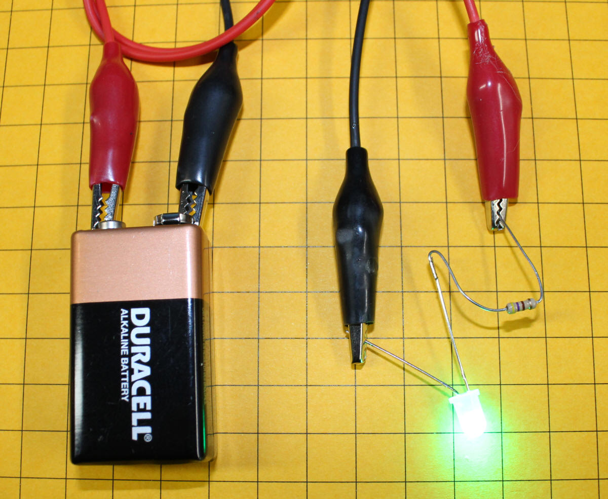
LED’s I just picked up for the headlights(from the Hobby Shop listed as a bright white also come with a 470 OHM resister and works well for those. You need to install the resister on either connector of the LED. The metal connector can be shortened to fit your needs but don’t over do it as when you solder the wire and or the resister to it you don’t want to get the wire very hot. Be sure to use heat sinks between your solder joint and the resister, LED, or what ever. A heat sink is just a metal clip that will absorb extra heat before it gets to the item you are installing. You can get them at most electronic stores and they are not that much. Worth the investment. For some lights a headlight brightness may be to much. Therefor changing the resistor to a higher resistance can do the trick. The best way to experiment with these is to have a small experimental PC board to connect your parts without soldering them to see the results. Also using wire clip connecting leads will do the same thing. This is a good way to check your results before you solder everything together and find you didn’t like the results and have to tear it all apart. LED’s that I have gotten so far have a larger electrode and a smaller thin electrode in them. The larger one will get hooked to your positive power lead such as your white wire coming off your digital chip. The thin electrode will get connected to the common or ground side. which on a digital chip would be the blue wire. I don’t know if they are all that way but so far that is what I have run into. The one’s I have recently done (if you reverse the positive and ground they will not work. Take notes and draw your circuit out with the resister you used and the LED. This will help later when you want to install the same thing somewhere else on your layout.
As I will be doing,headlights but I will also be doing dwarf signals to identify which way a switch is set. and I will be using smaller LED’s and probably different resisters. Hooking these circuits into a switch motor can be for another subject. Happy Railroading from Newman Atkinson