
Everything on model trains, model railroads, model railways, locomotives, model train layouts, scenery, wiring, DCC and more. Enjoy the world's best hobby... model railroading!
 Jim models HO and asks readers:
“Does anyone have an easy way to wire reed switches to a layout? Specifically, cylindrical reed switches. Thanks. ”
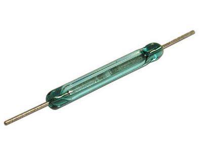
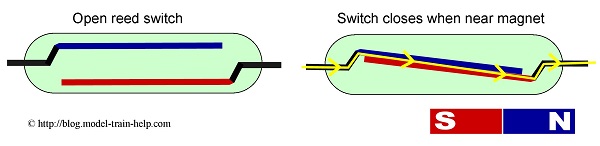
A reed switch has two metal reed contacts enclosed inside a glass cover. One contact works like a North magnetic pole and the other a South magnetic pole. The reeds spring together when near a magnet, which lets the current flow. When removed the reeds split apart and the current stops flowing.
In simple terms, a reed switch works like a ‘drawbridge’ in an electric circuit. A closed switch has the ‘bridge’ down so the current can flow through the circuit; an open switch has the ‘bridge’ up so no electric current flows.
The reason for having a reed switch is to activate (or deactivate) a circuit when needed. Some railroaders use a reed switch and glue a magnet under their locos for train detection.


Wiring up that reed switch would be the same as wiring up a SPST switch.
It’s just on and off for a single circuit. No bigger.
I would use the small “Female” connector pins used in “MOLEX” connectors if glue mounted switch.
Less strain than soldering to them.
You can also get change over reed switches which act as SPDT switches and can be used in a break when magnet present mode.
I have used these on my layout to operate crossing signals I routed out a space that would hold the reed switch and I soldered the wires to the leads of the reed switches. the reeds control a series of relays that operate the flashing crossing lights. I put heat shrink tubing over the soldered joints. A word of warning do not bend the leads from the switches as this can break the glass tubing of the switch. A small powerful magnet glued to the bottom of the loco operates the switch. as the engine passes over the reed switch a self latching relay start the lights flashing and a second reed switch operates a second relay unlatching the first relay that stops the lights flashing. a second set of reed switches operates the lights of a train running in the opposite direction.
Please may I correct a technical error in the original post ?
The contacts in a reed switch do not have “magnetic poles”. The contacts are not magnets themselves, but are paramagnetic. They only become magnetic when an external magnetic field is applied, and only then attract each other and close the switch.
(If the contacts were permanent magnets, the switch would be permanently closed.)
The diagram shows the contacts as being magnetic monopoles. According to Wikipedia:
“There is no conclusive experimental evidence that magnetic monopoles exist at all in our universe.”
I use these a lot on my n-scale layout. Place them between the rails, parallel to the rails – you should remove a tie or two so the switch can sit flush with the ballast. You can bend the leads downward and solder on a short length of light hookup wire to the ends. When bending, hold the lead with a needle-nose pliers at the edge of the glass, then bend on the opposite side of the pliers, away from the glass – this minimizes stress on the device. Glue a small size (1/4 inch or less dia) high-powered neodymium magnet to the bottom of a locomotive to trip the switch. I use these to stage trains in hidden areas, by pulling the train forward until the switch is tripped, lighting an indicator on a panel.
I have bent the connectors down toward the HO track (center of track) and soldered wires to them and run the wires through a hole between rail ties for electrical connection below the platform. I glued the magnets to caboose as to add weight to these lighter cars and for resetting the block behind to avoid collisions (just in case of derailment).
I have a HO train layout with two turnouts when I put a third turnout in the train will not run the turnouts are run manually no wires.
I cut two 3mm brass tubes about 30mm long and soldered a length of wire into one end of the tube. Drill a 3mm hole between the sleepers 3 spaces between holes. insert the brass tubes and tap down just below the sleepers. bend the wire of the reed switch ond insert into each brass tube. I then cut a small piece of cocktail stick and fitted it into the hole this makes a good contact with the reed switch wire. This can be painted black (if the reed switch should fail it can be changed very quick)