Planning
Everything on model trains, model railroads, model railways, locomotives, model train layouts, scenery, wiring, DCC and more. Enjoy the world's best hobby... model railroading!

John wants to hear from HO model railroaders about space requirements:
“Can someone tell me how wide must a table be to allow an HO train to make a turnaround? How much room do I need? I plan to put my layout on a banquet type table and the question is will the HO train make a turnaround on a 30″ or a 36″ table? Thank you so much for letting me post my question. I really appreciate it.”
Post your replies to John’s HO question using the comments link below.
Can anyone help this reader:
“Iam going be soon living with persons my own age have plan for lionel fastrck layout call for: 7 switch track remote, 1 left hand remote switch track and 6 right hand remote switch track. I was wondering how to wire them. Does anyone know the answer. The layout plans can be found at
www.thortrains.net/marx/48fastrack1.html The plan Iam looking at is a 4×8 layout the first one on the page.”
Ted would no doubt benefit from viewing John’s layout in my model train video series as John has set up a very compact HO layout in a small space. Anyway, here is Ted’s question and he would like feedback and ideas from readers:
“I have a space approximately 14 x 8 for a new HO layout (first time for me), but I have walls on two sides. How do I solve the problem of access to all track areas but still make good use of the space? Are there any “classic” layouts that would work particularly well in this type of space?”
James wants to hear from anyone who has added a golf course to their layout, or from anyone who has some suggestions:
“I would like to bring together my to hobbies, H.O. Trains and golf. I am putting together a new HO lay-out and would like to put in a 9 hole course with club house. Does anyone have any photos of this type of lay-out? I will use a u-shaped lay-out with the golf course at one end and a yard at the other end. Any photos or help on this would be helpful. Thanks.”
Add your feedback using the green comments tag below.
Bill would like to hear from anyone who can guide him with a layout plan:
A. I want to run N gauge – one passenger, one freight, and one switcher. Freight and switcher to start.
B. Initially one level with second level in future.
C. I have a fair amt of track (Atlas) switches (Atlas abt 7-8 l&R]
D. Space available – L shape 80″x36″, 36″x36″
E. What I’m looking for initially, I would like some of an idea OF A LAYOUT PLAN. I must start here in order to determine my costs. I’m 77 yo, retired on SS so I must work within a very tight budget. I’ve tried laying one out but get all messed up!
When you don’t know – go to the people who do know. CAN YOUR READERS HELP/GUIDE ME PLEASE.
To add your feedback click on the green comments link below.
A few weeks ago Tim sent in some info about the model train layout he is building with the help of his wife, uncle and nephew. He has now sent in some more details he would like to share with others in the hobby. He aslo gives some tips based on his experiences working on the RR project:
A combination of things then slowed my progress. My nephew came over two weekends after finishing the construction of the table and we began laying track on the table. I own several Accurail 89 ‘ foot car carriers so I wanted curves that could accommodate them.
Some days later, I took my wife out to dinner and after wards we headed to Lowes. I immediately searched for a dry wall saw and bought one along with several other tools.

Lessons learned and equipment being used:
I am principally modeling the Missouri Pacific though I have engines from the Southern Railway, Rock Island, and Illinois Central. I am attempting to model from the early seventies to the early nineteen eighties. I am loosely basing my layout on the old CE&I line bought out by Missouri Pacific in 1967. I initially wanted to have a small town with a single farm and a grain elevator for the industry, but I quickly learned that I didn’t have enough room on my 4X8 table.
I immediately simplified it to a couple farms and the grain elevator. In order to add some variety, I placed a river to the west end of the table and a highway overpass to cross a road over the mainline and servicing siding for the grain elevator.
The Highway Overpass
As part of my rr layout, I am building a highway overpass to cross a country highway over the main line and the spur lines at the elevator. The kit that I am using is a Rix Modern Overpass kit. It comes in 50′ foot road sections (measure 7 inches long) and the piers.
I started by painting the pieces; however, this turned out to be a bad idea. I primed them with gray primer spray paint and I then painted them with concrete gray. This creates a couple major problems. First, it makes it difficult to glue the pieces together.
Each foundation consists of holes where piers go. The holes helps hold the tubes in place plus they permit you to adjust the height of the bridge. Painted even with just the primer causes the holes to be almost too small for inserting them. You will most likely tear up the tubes or the pieces that you are inserting them into.
Once I got my first hill up, I realized that my pier was too high (full height is 6 inches). I tried cutting it down, but that caused the plastic to tear. I then had to start over.
Recommendation
Measure the height of the area to be crossed to determine the height for your piers prior to building them (if you need taller piers the company recommends that you use Plastruct tubing).
I also recommend measuring the distance you intend to cross so you can glue the appropriate number of road sections together. This permits you to line up your “I” beams and glue it more securely. Use a strong glue like a gap glue for assembling them due to the weight.
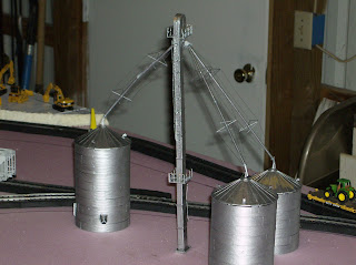
The Grain Elevator
This is also a Rix kit. As stated earlier, I found gluing this together to be difficult. Just before Thanksgiving, I traveled to a new hobby store in Marion, IL called “Chuck’s Depot.” The owner suggested that I use a glue made by Faller called “Expert: Plastic cement” for working with the Rix products. This glue worked adequately to build the conveyor leg shown below.
You must buy the conveyor leg and its bins separately. Technically, it comes with plenty of parts between the grain bin and the leg, but if you make some mistakes or lose some parts you’ll come up short quickly.
Rix’s produces an expansion kit and another that provides extra parts for the bins; however, they don’t yet provide any for the conveyor leg. It requires two auger pipes to connect the leg to a 44′ foot grain bin. Each tube provided is 5 inches long so I cut one inch from each pipe to make them eight inches. I found the Faller’s glue not strong enough for the auger pipes. I recommend a gap glue for those. I put the augers on last and this created all kinds of problems.
In building a second conveyor leg, I glued the parts that hold the pipes in place to the “head” prior to assembling anything else. It allows you to hold pressure to insure adequate bonding without damaging the details on the leg.
I am also planning to use Evergreen styrene tubes for the augers instead of the tubes provided (more on that in a later article). Use a strong glue due to the weight of holding the pipes up (I used Gap glue). I also used Gap glue to glue the platforms together. Don’t wait for the platforms to dry before assembling to the leg. They must be flexible enough to wrap around the leg. I used the gap glue to glue the cage that goes around the ladder. You may use any glue for putting the sections of the leg up. For support wires, I used regular thread, I found the support wires provided with the kit too flimsy. I tried 15 pound test fishing line. This has too much torque and it wants to pull away from the glue and bends the augers.
To submit details of your layout for publication go to http://www.model-railroad-resources.com/my-layout.html
Doug wants to hear reader recommendations on building a layout his Grandchildren can enjoy:
“Perhaps someone can advise me on the following. I am looking atbuilding the Transbay Interwoven ( Atlas 7X7 step#13) but I cannot findanywhere a plan showing scenery or finished layout to give me finalperspective.
This is my first attempt at building, we had one as kids and now I wantto do this with my Grandchildren, or is there a better layout your readers can recommend that will give two trains agood run and rise through mountains and over rivers etc. Thank you so much for offering this service.”
About the Transbay Interwoven Layout:
Features one train passing over another. The Transbay Interwoven does this by using elevated track provided by the Atlas pier Set. A minimum table size of 6′ x 10′ is needed to construct the Transbay Interwoven with track around 79 feet.
To add some feedback click on the green comment link below.
Thank you for the excellent feedback on my series of model train videos – I’m glad people are enjoying them.

Video #23. Making Scenery Foliage

Lance has a question for you:
“I have a question for your readers. I have a remodeling company and one of my customers wants to put a train around the perimeter of his basement and I was wondering the easiest way to do so Ithought bout nailing a 2×4 up bout 12″ from ceiling and then putting a 1×6 nailed to top of it to hold the track? Has anyone got any good suggestions?”
To comment use the green comments link below.
David has a question for readers about software for model railroad layout design:
“I wish to use my computer to design my HO scale railroad. What software packages are there to use, and how do they differ? What do the model railroading magazines use to generate those nice designs? Hopefully a reader will be able to guide me. Thanks in advance.”
Keen model railroader “Guy” has an HO layout based on a drawing from John Allen’s ‘Timesaver’ switching. Here is what Guy has to say:
“Hi folks! This is the first layout I’ve created. It is based on the drawing from John Allen’s famous switching game called Timesaver. The entire track is handlaid on wooden ties with code 70 rail. The five turnouts, the 11 uncoupler magnets and the track lengths correspond to the given instructions from John.
I find it a lot of fun to operate this layout and even at a model exhibition people were interested to follow all the shunting work.
For best operating results, I operate my engines in DC mode with a small controller (faster shunting). For smooth and realistic operation with sound a LocoNet DCC unit is connected.
The turnout is manual control with a pushrod that activates a switch for frog polarity. The switchstand really works and indicates the position.
Wherever you go, this small layout is ready in a few minutes and the operation can be started with one Loco and some cars.”
This question is similar to one already published on this blog. If you want to help Joe then click on the green comments link below this posting:
“Last year I visited a local insurance agency whose owner was a model railroader. To my surprise and delight I noticed that he had created a layout that ran around the entire perimeter of his office and was mounted about ten feet in the air. He had skillfully crafted a bridge network that cantilevered off the wall to hold his HO gauge track. The bridge looked very realistic and cantilevered in an “L” type shape off the wall.
I’ve looked for something like this that I could build myself as my wife has agreed to let me build my own layout on our basement walls. Do your readers have any idea where I might be able to get access to these type of bridge plans?

If you would like comment on Marty’s plans for give him some suggestions, click on the green comments link below.
Another Robert shares some info on his planned OO Gauge layout:
“My layout will be in the loft approximately 16 ft x 12 ft. I have all the timber for the baseboard, but I have not started construction yet. My locomotives will be mainly London Midland & Scottish and Souther Railway with possibly a Great Western Railcar,Flying Scotsman, GW 0-4-2 Tank, GWR Castle/King/County/LNER A1 Tornado/LNER B14-6-0 No 61264(I sat on this loco in the scrapyard. Your readers might have some ideas to help me?”
To comment on this posting click on the comments link below.
John is planning on building a new HO layout and would like feedback from readers:
“I am planning out an HO model RR project to run from Boston Ma, through to New Hampshire and Maine. I am basicly a rookie, although I have built several small layouts. The last one I built had upper and a lower levels. I had 2 trains on it. I realize this is going to be quite an under-taking but I haven’t seen a lot of N E rail setups of NH or Maine connected or from Boston. I have cut some of my buildings from styrofoam to match the 1960’s era. If your readers have any ideas to keep it simple, I’ll thank them in advance.”
To comment on John’s planned HO layout click on the comments link and have your say.
Mike has sent in details about his 14th Street Yard HO layout:
This HO layout represents a small yard in the downtown area of an American city I’m not going to name. The Yard is surrounded by various industries, most of whom use the railroad for delivery or despatch.
The track plan is based on the ‘Timesaver’ concept pioneered over 60 years ago by John Allen. The layout is not only a model railway but a fascinating logic puzzle.
Each industry and freight car is assigned a coloured pin. The object of the game is to match the coloured pins on the tops of the cars with the coloured pins at the industry. (The car with a red pin goes to the industry with a red pin and so on.)
The game is over when all the pins match. The game is restarted by changing the pins on the cars and beginning again.
Other rules:
1) All moves at realistic speed.
2) No touching by hand including uncoupling.
3) The grade crossings can only be blocked for a maximum of 4 moves.
4) Cars are only sent to realistic locations. (A flatcar of timber is unlikely to be delivered to a book publisher!)
Details:
Alex share information about his HO Pacific and Southwestern layout.
“My layout is about 20×20 feet. It is located in my garage and stretches around the walls and has double decked layouts. The benchwork is from the idea of the great lionel strange of odel railroader. It is 1×4 in L shaped and meatal L brackets for support. I used 2” thick extruded pink foam for the base. Ho cork roadbed is used for subroad bed in certain areas and otherwise track is laid straight to the foam.
The track is atlas code 100 for main line and atlas code 83 for sidings and yard. Ihave 30″ radius on all my curves for eaiser transitions for my longer cars. My layout is the era of the late 70 to late 80.
Club members at my RR club have also put time and effort into helping me build this HO layout (which has been in progress for two years now). I use woodlen scenics ground foam for scenery and also real dirt. my son and myself have made all the trees from scratch. A really good friend and club memeber has built most of the power plant and also the mountain and bridge in the corner scene.
The yard is named after my grandfather. Most of the structures are named after either family members or friends. Another good friend has detailed all of my locomotives and even sctach built my santa fe sd-26.
I weather all my cars and they all have kadee metal wheels and kade couplers before the can be on the layout. I use dcc from digitrax. Another friend has done a great deal with helping in the wiring dept.
I still have a long ways to go and I truly believe the layout is never finished but that is the enjoyment of the hobby. The layout is mostly based on the union pacific but I do have interchange with the santa fe, southern pacific and the rio grande.
Most say I should model the csx because I live in Florida, but I grew up in California and this is from my childhood memories.
To comment on Alex’s posting click on the green comments link below.