Everything on model trains, model railroads, model railways, locomotives, model train layouts, scenery, wiring, DCC and more. Enjoy the world's best hobby... model railroading!
Two Train Wiring

Leon wants some free advice from others in the hobby and asks:
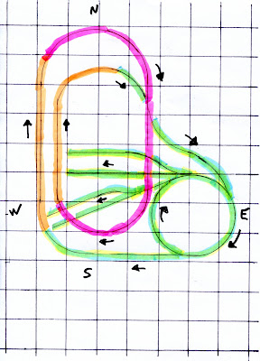
“Can anyone help me wire this layout for 2 train operation? Here is my layout. On the plan, each square is 12 in. by 12 in. The actual size of layout is 8 feet N to S, 7 feet E to W, at widest points. Colour code: green is lower level; orange is up and down grade; red (pink) is upper level. Scale is S, American Flyer, old type track.”
Add your comments below.
One Response to Two Train Wiring
Leave a Reply


Leon,
Looking at your track plan perhaps the easiest (but most expensive) way to get two train operation is to convert your equipment to DCC control.
Another option is to break the track plan into separate electrical blocks (or sections) and operate what is called ‘cab control’. You’ll need two transformers and, depending on how many sections you create, a number of double pole, double throw, center off (i.e., DPDT) electrical switches, one for each block. Each block length should be at least as long as the longest train you expect to run.
After you have isolated the track’s blocks using insulated rail joiners in each rail, start by running power leads from the track to the two center ‘poles’ of the DPDT switch. Be sure that you are connecting the wiring the same way on ALL the DPDT switches. For example, the inside rail wiring on a theorectical track loop should be connected to the right hand side center terminal or pole of DTDT switch and the outside rails to the left side center terminal.
Once the above connections are complete, connect the power leads from one of the transformers to one pair of terminals on each the DPDT switches. As before, make sure you are connecting to the same pairs on the DPDT switches so you can easily remember which transformer is in use based on the DPDT handles position. Try to use different colored wires to keep track of which wire is coming from where. Connect the second transformer to the remaining DPDT terminal pairs.
At the risk of stating the obvious, you’ll have to make a control panel of sorts to mount the DPDT switches into (1/4″ plywood works well). Mount the switches so that when the DPDT switch is in the ‘UP’ position, transformer A will be sending power to that track section. When the DPDT switch is in the ‘DOWN” position, transformer B will be sending power to the same track section. Setting the DPDT switch to the ‘CENTER’ position will kill power to the section altogether.
When you operate your equipment, you’ll have to keep track of where your engines are so that the DPDT is in the correct position to accept oncoming trains into empty blocks. To say it in a different way, if you are running a loco with transformer A and it enters a electrical section whose DPDT switch is in the transformer B position, transformer B will now control the locomotive. If, in this example, transformer B is off, the train will stop or if it is set in a reversed mode, the train will reverse when it enters the block (section).
As a general comment, I suppose it is possible to run two trains at once on this layout without doing ANYTHING providing your transformer is powerful enough to handle two locomotives at the same time. If they are far enough apart they shouldn’t run into one another but they’ll both respond in the same way if you change speed or stop though you have probably figured this out already.
There are a number of model railroading books out there that will explain cab control wiring better that I did but you get the idea. I should also mention that Atlas Model Railroading Inc. has an electrical device called ‘The Selector’ that does most of the hard wiring for you (around the DPDT switches at least) and is quite inexpensive.
Hope this helped,
Geof